


Electrical gremlins
 8 March 2013
The subject of this month’s diagnostic feature is a standard, cooking model 2007 Vauxhall Astra. The customer bought the Astra a year or two ago after a horrendous and expensive ownership experience with a Renault Scenic. Most of his Renault woes stemmed from electrical gremlins. When buying his next car, the Astra, he specified a low spec model as he thought the absence of technology, whizzy gadgets and unnecessary features would lead to a more reliable mode of transport. Unfortunately, this proved not to be the case.
The vehicle developed a fault where it failed to crank. Initially, it was suspected that the battery had gone flat but after a recharge, the symptom remained the same. He took the vehicle to his local garage who ‘came to the conclusion’ that the vehicle was suffering from a ‘CAN’ fault and recommended it be referred to a specialist.
Upon initial inspection, the vehicle presented a ‘no crank’ symptom similar to a faulty immobiliser but there was a lack of the tell-tale flashing immobiliser light. After a visual inspection, I performed an ECU presence check. This process attempts to communicate with the modules which the vehicle ‘believes’, through coding (usually of the ‘master’ or gateway ECU), should be available and presents a summary of diagnostic trouble codes.
Network topology
An ECU which reports as being not present indicates that it is not coded (i.e. the vehicle believes that this option is not and shouldn’t be present). An ECU which reports a status of ‘no communication’ means that the vehicle believes that it should be part of the network but it cannot communicate effectively. This is a subtle but important distinction. It is possible that the vehicle can lose or have corrupted coding. This is normally caused by a power failure (very flat battery) or a voltage spike (jump or booster packs), or the replacement (and non-coding) of an ECU.
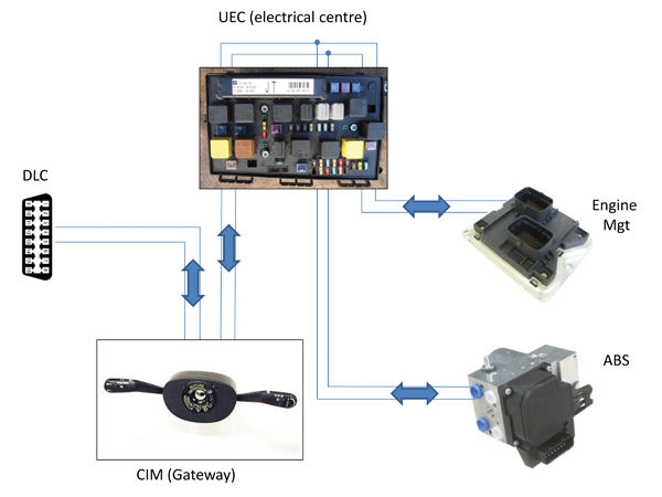
A vehicle scan showed that several ECUs were unable to communicate. Although this situation won’t provide the root cause of the fault, understanding which are affected and how they are connected may help to identify the next step. An important element of the CAN Bus fault finding process is to determine the physical layout, wiring and interconnection between the various ECU’s. This is known as the network topology, see Figure 1 for a topology diagram. Some aftermarket information providers have this data in their products.
Generally, the vehicle networks are split into functional clusters, grouped by speed. These are generally known as High (Powertrain), Medium (internal body) and Low speed (non-core body) networks. They speak a different ‘language’ which is translated and shared through the gateway. Information must be able to pass between the different networks. Understanding the topology and analysing the system’s function chain will help to diagnose the root cause much more quickly.
It is largely a case of ease of access which dictates where in the affected network the scope is placed to measure the signals. Technicians should take a look at the vehicle, in conjunction with the topology diagram, and choose the easiest access point. Traditionally, tests were carried out at the Data Link Connector (DLC) however, some vehicle manufacturers don’t take the Powertrain CAN to the DLC, choosing instead to interface the scan tool through a different protocol to a diagnostic interface ECU. In this case, CAN testing at the DLC isn’t possible. The next most convenient location will be at the connection blocks of one of the under bonnet powertrain ECUs (either ABS, EHPS, Body Controller or Engine).
Many manufacturers use standard colours for the CAN signals (in this case, Vauxhall use green and white). The ABS control unit on this vehicle is easy to access, so the next step is to connect the scope, via a back probe, into the CAN to see what’s going on. The waveform in Figure 3 was measured. A quick cross reference to Diagnostic Assistance and Figure 4 showed that the shape of this signal was incorrect.
All we can tell from the waveform is that the CAN is being corrupted but we don’t know why. The likely causes are a wiring fault (short/open/too much resistance) or an ECU failure. Any of the ECUs or the wiring on the powertrain CAN could cause this. I decided to test the wiring first as this is quick and easy. Turning off the ignition and leaving the vehicle for a few minutes will let the CAN go to sleep. By back probing the ABS ECU with the multimeter, set to resistance, I should see 60 Ohms (the value of the two CAN termination resistors) all being well. I measured 60 Ohms, so my fault wasn’t in the wiring.
Figure 3: